Down hole Completion Accessories
In order to provide Localized and fit-for-purpose production that meets customer needs, HTD’s design team is qualified to redesign available productions to acquire specific technical requirements in functioning, strength and corrosion resistance performance, as well as to preserve the consistency and interoperability with other original types.
The HTD Product Catalog has been compiled to give our customers an indication of our product range and capabilities.
Fluted Swage & Adapter
Applications
The HTD Fluted Swage/Adaptor is designed to use between the tubing/tools string up to safety valve’s landing nipple. In the external surface of the Fluted swage/adaptor some slots machined which allow control line to be placed into and also get protected from any damage during the tubing movement.
Ordering information:
Please specify type and size of threads, tubing, weight and grade of working pressure and temperature, percentage of H2S and CO2.
| Tubing Size | Casing Size | Casing Weight (PPF) | Max. OD. (in) | Pressure Rating (psi) |
|---|---|---|---|---|
| 5” | 7” | 29 | 6000 | 7000 |
| 7” | 9-5/8” | 36-47 | 8.500 | 5000 |
| 5” | 7” | 29 | 6.000 | 10.000 |
| 7” | 9-5/8” | 36-47 | 8.500 | 10.000 |
Fluted Swage & Adapter
Applications
The HTD Flow Coupling is used to protect the integrity of tubing from erosive turbulence. Flow couplings are often used above and below a geometric restriction in the flow path, depending on the well conditions. API recommended practices 14B advises use of flow couplings above and below safety valve.
Ordering information:
Please specify type and size of threads, tubing, weight and grade of working pressure and temperature, percentage of H2S and CO2.
| Tubing Size | Max. OD. (in) | Connection | Pressure Rating (psi) |
|---|---|---|---|
| 5” | 5.625 | NEW VAM 5” 18# BOX x PIN | 7000 |
| 7” | 7.720 | NEW VAM 7” 29# BOX x PIN | 5000 |
| 5” | 5.625 | NEW VAM 5” 18# BOX x PIN | 10,000 |
| 7” | 7.720 | NEW VAM 7” 29# BOX x PIN | 10.000 |
Mill Out Extension
Applications
The Mill-Out Extensions provide a large ID below the packer seal-bore, which allows a single-trip packer milling tool to be used when tubing is run blow the packer assembly.
Ordering information
Please specify type and size of threads, tubing, weight and grade of working pressure and temperature, percentage of H2S and CO2
| Tubing Size | Max. OD. (in) | Connection | Pressure Rating (psi) |
|---|---|---|---|
| 5” | 5.039 | NEW VAM 5” 18# PIN x PIN | 7000 |
| 7” | 7.039 | NEW VAM 7” 29# PIN x PIN | 5000 |
| 5” | 5.039 | NEW VAM 5” 18# PIN x PIN | 10,000 |
| 7” | 7.039 | NEW VAM 7” 29# PIN x PIN | 10.000 |
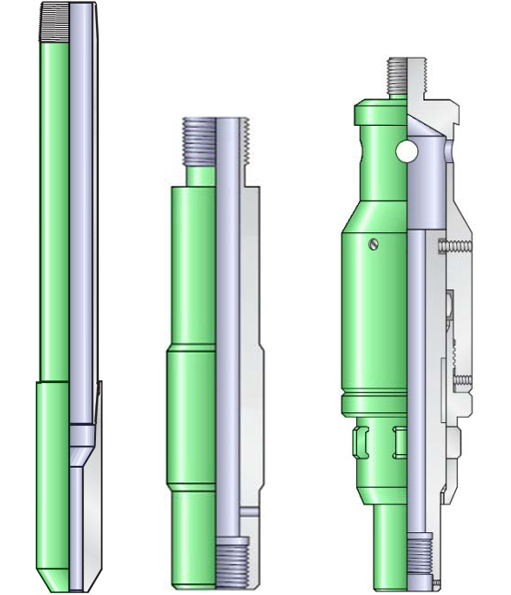
Top No Go Nipple
Applications
- The HTD Surface Set Seating Top No-Go Nipples are down hole tubing nipples that provide for the location of various wireline flow control devices in the production string. The location and number of Top No-Go Seating Nipples should be carefully considered in the completion planning stages to allow maximum versatility in the positioning of various flow control devices. These Nipples contain a no-go shoulder above of seal bore and a locking groove. The no-go shoulder is used to locate and set the flow control device that is being run into the well. When running the flow control device in the well, a no-go shoulder located on the flow control device will come into contact with the no-go shoulder of the seating nipple.
Features
- Honed sealing bores for maximum sealing performance.
- Seal-bore contoured and polished to pass packing without damage.
- Integral locking groove.
Benefits
- Land instrument hangers with geophysical devices such as pressure and temperature recorders.
- Extended upper nipple bore eliminates pre-setting.
| Tubing Size | Seal Bore Size | No-Go ID | Pressure Rating |
|---|---|---|---|
| 41/2” | 3.125 | 3.072 | 10,000 |
| 3.312 | 3.256 | 10,000 | |
| 3.437 | 3.347 | 10,000 | |
| 3.688 | 3.625 | 10,000 | |
| 3.812 | 3.759 | 10,000 | |
| 51/2” | 4.125 | 4.035 | 10,000 |
| 4.312 | 4.255 | 10,000 | |
| 4.562 | 4.470 | 10,000 |
Lock Mandrel Assembly
Applications
The HTD Lock Assembly is the Surface Set line of Top No-Go Locks. It is mechanical devices used to position and secure wire-line retrievable equipment in appropriate type nipples which are located in the tubing string. These locks provide a smooth interior for minimum pressure drop and maximum fluid flow. The large bearing area and the angle of the bevel on the locking dogs enable the Surface Set Locks to hold high pressure without damage. The no-go shoulder in the seating nipple is used only to locate the lock. Once the locking dogs are fully extended in the nipple’s locking groove.
Features
- Simple and rugged construction.
- Locking mechanism is located above the sealing elements; therefore, no O-rings are required.
Benefits
- Smooth bore through the lock does not subject the operating mechanism to corrosion or sticking by foreign materials.
- Running tool gives a positive indication that the lock is set in the nipple and the locking operation is complete.
| Seal Bore Size (in) | Fishing Neck Size (in) | No-Go OD (in) | Pressure Rating (psi) |
|---|---|---|---|
| 1.875 | 1.380 | 1.935 | 10,000 |
| 3.125 | 2.620 | 3.200 | 10,000 |
| 3.312 | 2.620 | 3.375 | 10,000 |
| 3.688 | 3.120 | 3.740 | 10,000 |
| 3.812 | 3.120 | 3.870 | 10,000 |
| 4.125 | 3.120 | 4.200 | 10,000 |
| 4.312 | 3.120 | 4.390 | 10,000 |
| 4.562 | 4.000 | 4.650 | 10000 |
| 5.950 | 4.250 | 6.020 | 10000 |
| 5.963 | 4.750 | 6.025 | 10000 |
Separation Sleeve
Applications
The HTD Separation Sleeve is used to isolate the safety valve landing nipple from well bore pressure by sealing in the upper and lower seal bores. This accessory tool is used primarily to prevent well bore contaminants for entering the control system.
Features
Reliable seals – packing sealing in polished bores isolates tubing pressure from control line pressure.
Benefits
Seal bore protection – the separation sleeve protects seal bores during wireline operations.
| Tubing Size | Seal Bore Size | Drift ID | Pressure Rating |
|---|---|---|---|
| 5” | 3.812 | 1.961 | 10,000 |
| 7” | 5.950 | 3.142 | 10,000 |
| 7” | 5.963 | 3.263 | 10,000 |
Perforated Joint
Applications
The HTD Perforated Joint is a spacer tube that used at the end of a tubing string to provide an alternate flow path in cases where wire-line measuring devices are used.
Ordering information:
Please specify type and size of threads, tubing, weight and grade of working pressure and temperature, percentage of H2S and CO2
Wire-Line Entry Guide
Applications
The HTD wire-line Entry Guide with Half Mule Shoe bottom is designed to be run on the bottom of the tubing string. It will aid wire-line tools re-entry into the tubing.
Ordering information:
Please specify type and size of threads, tubing, weight and grade of working pressure and temperature, percentage of H2S and CO2.
Cross-Over
Applications
The HTD Tubing Crossover used often when need to change thread size or type in the tubing string to connect completion equipment with different thread types or sizes.
Ordering information:
Please specify type and size of threads, tubing, weight and grade of working pressure and temperature, percentage of H2S and CO2.
Instrument Hanger
Applications
- The HTD Sur-Set Lock Assembly with instrument hanger adaptor is used to enable the locks to serve as a down-hole instrument hanger to land and lock geophysical instruments into a seating nipple.
Ordering information:
- Please specify type and size of threads, tubing, weight and grade of working pressure and temperature, percentage of H2S and CO2.
Two-Trip Bypass Blanking Plug
Applications
- The HTD Two-Trip Bypass Blanking Plug with removable mandrel is a positive blank-off device designed to seal off pressure from above and below. These plugs are for use in wells where sand or sediment might be encountered. The removable mandrel protrudes from the fishing neck of the lock so that a sand bailer can expose the top of the mandrel for retrieval. The Model GH Plug may be used with either the top no-go or bottom no-go type locks. Equalization is accomplished by pulling the removable mandrel from the plug and opening the bypass ports to pressure. The plug itself is then pulled using conventional running and pulling tools.
Features
- Smooth bore through the lock does not subject the operating mechanism to corrosion or sticking by foreign materials.
- Running tool gives a positive indication that the lock is set in the nipple and the Locking operation is complete.
- 10,000 psi (690 bar) is defined as working pressure.
- Special sizes and Profile are available upon request. 1.875, 2.562, 3.125, 3.312, 3.688, 3.812, 4.125, 4.312, 4.562 inch are common seal bore sizes in HTD design.
- The Product can be supplied in the following materials:
L80-T1 (4140), L80-T2 (9%Cr), L80-T3 (13%Cr).
Running Tool
Applications
- The HTD Running Tool is used to run and set all Sur-Set Lock assemblies. It has been designed to prevent accidental setting even if tight spots are encountered while running in the well. The running tool and lock will not separate until the locking dogs on the locking mandrel are fully expanded into the nipple locking profile. If this does occur, the running tool will not release and will bring the lock back out of the well when retrieving the running tool. Running Tool is designed to be used in conjunction with the Probe.
Features
- Several lock sizes can be run with same running tool.
- Running tool simply constructed–no Collets, springs, or plunger to move up or down to manipulate lock into a locating position.
- Indicator in running tool for surface set.
- In case the lock is not properly set in nipple, lock will return whit running tool.
- Special sizes and Profile are available upon request. 1.875, 2.562, 3.125, 3.312, 3.688, 3.812, 4.125, 4.312, 4.562 & 5.950 inch are common seal bore sizes in HTD design.
- The Product can be supplied in the following materials: L80-T1 (4140), L80-T2 (9%Cr), L80-T3 (13%Cr).
Running and Pulling Tool
Applications
The HTD “HS” Running/Pulling Tool is a basic wire-line device which connects a wire-line tool string to a wire-line retrievable flow control device that is to be run into or retrieved from a well. The “HS” Running/Pulling Tool is designed to engage an internal type fishing neck. The tool is offered in a wide range of sizes. It has been designed to prevent accidental setting even if tight spots are encountered while running in the well. The running tool and lock will not separate until the locking dogs on the lock are fully expanded into the nipple locking profile. If this does not occur, the running tool will not release and will bring the lock back out of the well when retrieving the running tool.
Features
- Several lock sizes can be run with same running tool.
- Indicator in running tool for surface set.
- Jar down to release.
• In case the lock in not properly set in nipple, lock will return with running tool
Applications
The HTD “HB” Running/Pulling Tools are basic wire-line devices that establish the connection between a wire- line tool string and a subsurface flow control device that is to be retrieved from its operating location in a well. Although designated a Pulling Tool and widely used for that purpose, in some instances the operating characteristics of the type “S” Pulling Tool also make it particularly suitable for use as a running tool to run and set certain flow control equipment. The major identification operational characteristic of “HB” running/pulling tool its jar down release feature. (It is released or disengaged from flow control device in a wall by jarring downward with sufficient force to shear the shear pin) in the tool.
Features
The “HB” pulling tool is especially designed to engage any type of device that has standard external fishing neck.
- Special sizes are available upon request. 1.875, 2.562, 3.125, 3.312, 3.688, 3.812, 4.125, 4.312, 4.562 & 5.950 inch are common seal bore sizes in HTD design.
- The Product can be supplied in the following materials: L80-T1 (4140), L80-T2 (9%Cr), L80-T3 (13%Cr).
Shifting Tool
Applications
The HTD Shifting tools are used to move the inner sleeve to its open or closed position in Sliding Side-Door Circulating Devices. The positioning tool engages the recess in the upper (or lower) end of the inner sleeve to permit the sleeve to be shifted by a jarring action.
The tool is designed to release itself only after the sleeve reaches its fully open or closed position. This automatic-releasing feature incorporates a releasing profile on the key itself that acts to compress the key spring and release the positioning tool. A shear pin is an added feature designed to release the tool in the event well conditions make it impossible to shift the sleeve.
A set of positive keys is available for this tool to permit upward movement of the inner sleeve of one among several sliding side-door circulating devices in one wellbore. These keys do not have a releasing profile. The positioning tool pin must be sheared to release.
- Special sizes and Profile are available upon request. 3.688 & 4.562 inch are common seal bore sizes in HTD design.
- The Product can be supplied in the following materials: L80-T1 (4140), L80-T2 (9%Cr), L80-T3 (13%Cr).
Kick-Over Tool
Applications
- The GBI Kick-Over Tools are wire-line service tolls that are used to install side pocket subsurface control devices into GBI side pocket mandrels, or to retrieve those devices as required. These tools must be used with either a running or a pulling tool. Especially suited for use in highly deviated wells, the kick-over tool consists of a fishing neck with a threaded pin connection on the upper end, a locating finger, kick springs, an arm assembly with a box thread connection on the lower end for attachment to a running or pulling tool and an arm housing with a nose on the lower end.
An upward movement of the tool through the chosen mandrel will position the locating finger in the mandrel orienting sleeve and rotate the tool into alignment with the mandrel pocket. The kick springs then pivot the arm to kick the attached running tool and control device or pulling tool outward, directly above the mandrel pocket. The arm housing protects the arm attached devices during installation and retrieval.
Features
- “OK1” kick-over tool used to install 1” OD Valves into “GKBMG” side pocket mandrel.
- “OM1” kick-over tool used to install 1.5” OD Valves into “GMMG” side pocket mandrel.
- Special sizes and Pressure are available upon request.4 & 5-1/2 inch are the common nominal size in HTD design.
- The Product can be supplied in the following materials: L80-T1 (4140), L80-T2 (9%Cr), L80-T3 (13%Cr).
Other Completion Accessories
Wire-line Retrievable Latch
Applications
- The HTD Latch is wire-line latch designed with a spring loaded latch ring to be used on top mounted gas lift valves, dummy valves, chemical injection valves and other side pocket flow control devices which are not provided with integral latches.
- The Latch is installed and removed from the mandrel pocket using standard wire-line methods. A minimum amount of force is required to install the latch. This is particularly important in deviated wells where forceful downward jarring is not possible.
Retrievable Dummy Valve
Applications
- These HTD Wire-line Retrievable Dummy Valves are installed in side pocket mandrels as a non-equalizing isolation tool. The Dummy Valve is available in either stainless steel or nickel alloys for corrosion resistance in wells with high concentrations of H2S or CO 2. Packing for the valve is available for standard service or special service to suit individual well conditions. The distance between the packing stacks is maximized to fully protect the mandrel pocket seal bores from produced fluids until they are removed from the completion. The simple design of the dummy valve allows for easy replacement of the packing. The rugged, solid construction and quality materials provide for a long service life. The HTD retrievable dummy valve is used to bank off a side pocket mandrel ports to:
- Allow for production prior to the installation of gas lift valves.
- Blank off the side pocket prior to pressurizing the tubing to set a hydraulic set packer.
- Isolate the tubing flow from casing annulus for test purposes.
- Isolate tubing from casing annulus during remedial work such as acidizing or fracturing.
etrievable Chemical Injection Valve
Applications
- The HTD wire-line retrievable chemical injection valves are installed in a side pocket mandrels to control the injection of treatment fluids down-hole to control corrosion, harmful deposits or control hydrates in completions. The valve can be used in annular or injection control line application. Treatment fluids can be pumped through the valve continuously or intermittently. The valve is designed with a power spring which provides the closing force of the valve. The spring controlled test rack opening pressure is easily adjusted from outside of the valve without the need of disassembly. The spring loaded operation of the chemical injection valve allows accurate functioning of the valve regardless of well temperature.
Features
- Tungsten Carbide ball and seat for long life.
- Valve can easily be set in field location.
- Integral reverse flow check valve to prevent tubing to annulus or injection line communication.
- Check valve has combination resilient and metal-to-metal seal.