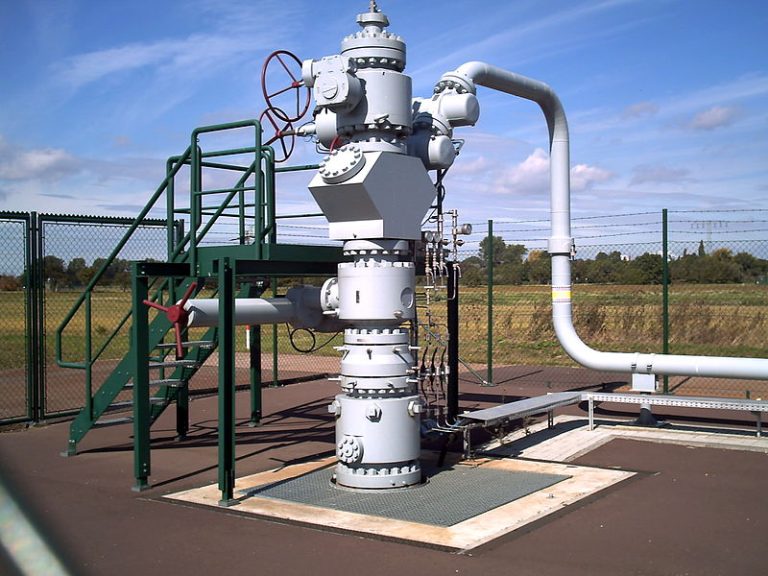
Casing Head
The casing head, installed at the bottom of wellhead assembly connecting casings and various wellhead assemblies, is composed of a body, casing hanger and seal assembly. The casing head is used for supporting the weight of technical and production casing, sealing the annual space between the casing and providing a filtered connection for the installation of upper wellhead assemblies. These assemblies include a blowout preventer (BOP), tubing head and Christmas tree. The surface casing is connected by a flange located below the casing head. The oil-string casing is connected by a screw thread inside of the casing head.
Casing Head Housing
The casing head housing is the lowest part of the wellhead assembly and is almost always connected to the surface casing string. The casing head housing serves suspend and seal a casing string. HTD’s Casing Head Housing is designed as follows:

| Bottom Size In | Top Flange | Side Outlets | ||
|---|---|---|---|---|
| Size In | Working Pressure Psi | Size In | Working Pressure Psi | 20 Buttress Box Thread | 21 1/4 | 2000 | 2 1/16 | 5000 |
| 18 5/8 Buttress Box Thread | 21 1/4 | 2000 | 2 1/16 | 5000 |
| 20 S.O.W (Socket On Weld) Box | 21 1/4 | 2000 | 2 1/16 | 5000 |
| 18 5/8 S.O.W Box | 21 1/4 | 2000 | 2 1/16 | 5000 |
| 20 Buttress Box Thread | 20 3/4 | 3000 | 2 1/16 | 5000 |
| 18 5/8 Buttress Box Thread | 20 3/4 | 3000 | 2 1/16 | 5000 |
| 20 S.O.W Box | 20 3/4 | 3000 | 2 1/16 | 5000 |
| 18 5/8 S.O.W Box | 20 3/4 | 3000 | 2 1/16 | 5000 |
| 18 5/8 Slip On Lock Box | 20 3/4 | 3000 | 2 1/16 | 5000 |
| 13 3/8 S.O.W Box | 13 5/8 | 3000 | 2 1/16 | 5000 |
| 13 3/8 S.O.W Box | 13 5/8 | 5000 | 2 1/16 | 5000 |
- Material Class: AA, BB, CC, DD, EE, FF, HH
- Temperature Class: SU (-60℃ ~ 121℃)
- Specification Level: PLS1 to PSL3G
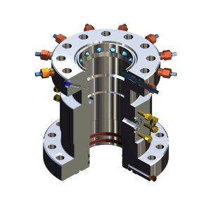
Casing Head Spool
Equipment attached to another casing head, which serves to suspend and seal a secondary casing string. Outlets are provided for annular access. Multiple casing spools may be stacked to hang intermediate and production casing strings. HTD’s Casing Head Spool is designed as follows:

| Bottom Flanged | Top Flanged | Side Outlets | ||||
|---|---|---|---|---|---|---|
| Size In | Working Pressure Psi | Size In | Working Pressure Psi | Size In | Working Pressure Psi | Seals In | 21 1/4 | 2000 | 13 5/8 | 3000 | 2 1/16 | 5000 | P-SEAL 13 3/8 |
| 20 3/4 | 3000 | 13 5/8 | 5000 | 2 1/16 | 5000 | P-SEAL 13 3/8 |
| 16 3/4 | 5000 | 13 5/8 | 5000 | 2 1/16 | 5000 | P-SEAL 13 3/8 |
| 16 3/4 | 5000 | 13 5/8 | 10000 | 2 1/16 | 10000 | P-SEAL 13 3/8 |
| 13 5/8 | 3000 | 11 | 5000 | 2 1/16 | 5000 | P-SEAL 9 5/8 |
| 13 5/8 | 5000 | 13 5/8 | 5000 | 2 1/16 | 10000 | P-SEAL 13 3/8 |
| 11 | 3000 | 11 | 3000 | 2 1/16 | 5000 | P-SEAL 9 5/8 |
| 11 | 3000 | 11 | 3000 | 2 1/16 | 5000 | P-SEAL 8 3/4 |
| 11 | 10000 | 11 | 10000 | 2 1/16 | 10000 | P-SEAL 9 5/8 |
| 11 | 10000 | 11 | 10000 | 2 1/16 | 10000 | P-SEAL 7 |
| 11 | 10000 | 11 | 10000 | 2 1/16 | 10000 | FS-SEAL 9 5/8 |
- Material Class: AA, BB, CC, DD, EE, FF, HH
- Temperature Class: SU (-60℃ ~ 121℃)
- Specification Level: PLS1 to PSL3G

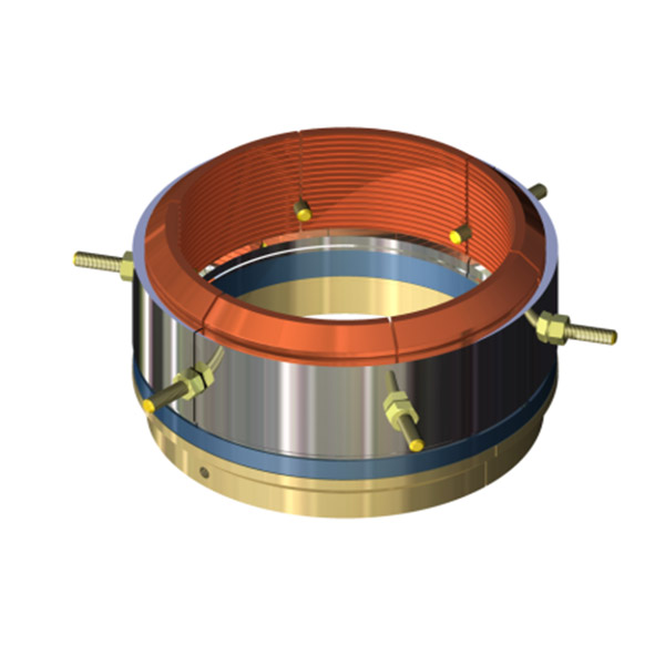
Casing Hanger
- It is a mechanism used to support a casing string in a casing head. Casing hangers are available with either threaded (mandrel) or slips. Slip-type hangers are available in automatic-sealing and no automatic-sealing varieties. Automatic hangers have seals which are energized by casing weight, while no automatic hangers have seals which require means other than casing weight to be energized. No automatic hangers are typically
- used when insufficient casing load is available or when cementing back to the surface. HTD’s Casing Hanger is designed as follows:
| Type | Automatic | Non-Automatic | Bottom Thread , In | Top Thread , In |
|---|---|---|---|---|
| Slips & Seal | P | P | X | X |
| Slips & Seal | P | P | X | X |
| Slips & Seal | P | P | X | X |
| Slips & Seal | P | P | X | X |
| Mandrel | X | X | 13 3/8 Buttress Box | 17.25-2tpi Stub Acme |
| Mandrel | X | X | 10 3/4 VAM Top Box | 11-4tpi Stub Acme |
| Mandrel | X | X | 9 5/8 Buttress Box | 10-6tpi Stub Acme |
Tubing Head
The tubing head is installed above the casing head and includes a tubing head spool and tubing hanger. The tubing hanger is used for hanging the internal tubing string and sealing the annular space between tubing and casing. This is used for conducting well flushing in direct circulation and reverse circulation, observing casing pressure, and for carrying out various tasks through the tubing and casing annular space.
Tubing-Head Spool
Piece of equipment attached to the uppermost casing head or smallest casing string which serves to suspend the tubing and to seal the annular space between the tubing and casing. Tubing head spool is similar to a casing head spool. It has a cone-shaped bore to accommodate the tubing hanger. HTD’s Tubing Head Spool is designed as follows:
| Bottom Flanged | Top Flanged | Side Outlets | ||||
|---|---|---|---|---|---|---|
| Size In | Working Pressure Psi | Size In | Working Pressure Psi | Size In | Working Pressure Psi | P-Seal In | 11 | 3000 | 11 | 3000 | 2 1/16 | 5000 | 7 |
| 11 | 5000 | 11 | 5000 | 2 1/16 | 5000 | 9 5/8 |
| 11 | 5000 | 11 | 5000 | 7 1/16 | 5000 | 9 5/8 |
| 11 | 10000 | 11 | 10000 | 2 1/16 | 10000 | 7 |
| 11 | 10000 | 11 | 10000 | 2 1/16 | 10000 | 9 5/8 |
| 11 | 10000 | 11 | 10000 | 2 1/16 | 10000 | 10 3/4 |
| 13 5/8 | 3000 | 11 | 3000 | 2 1/16 | 5000 | 9 5/8 |
| 13 5/8 | 3000 | 11 | 5000 | 2 1/16 | 5000 | 9 5/8 |
| 13 5/8 | 3000 | 11 | 5000 | 7 1/16 | 5000 | 9 5/8 |
| 13 5/8 | 5000 | 11 | 5000 | 2 1/16 | 5000 | 9 5/8 |
| 13 5/8 | 5000 | 11 | 10000 | 2 1/16 | 10000 | 9 5/8 |
| 13 5/8 | 5000 | 13 5/8 | 5000 | 2 1/16 | 5000 | 10 3/4 |
| 13 5/8 | 10000 | 13 5/8 | 10000 | 2 1/16 | 10000 | 10 3/4 |

- Material Class: AA, BB, CC, DD, EE, FF, HH
- Temperature Class: SU (-60℃ ~ 121℃)
- Specification Level: PLS1 to PSL3G
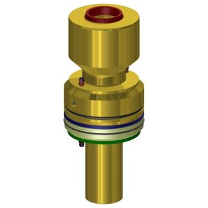
Tubing Hanger
Tubing hanger is a mechanism used to support a tubing string in a tubing head. It is available with either threads (mandrel) or slip.
Tubing hanging devices are often very simple. In many cases they consist of only a threaded hanger with a seal assembly on the tapered outside part that presses against the corresponding tapered part of the tubing head. The hanger is held in place by tightened screws in the upper flange. A length of tubing is screwed onto the upper female threaded part of the hanger so that it can be positioned. HTD’s Tubing Hanger is designed as follows:
| Size In | Bottom Thread | Top Thread | Back Pressure Valve |
|---|---|---|---|
| 11 (Nominal) 10 3/4 X 7 | New VAM / VAM Top | New VAM / VAM Top | 6 5/16 Type "H" |
| 11 (Nominal) 10 3/4 X 5 | New VAM / VAM Top | New VAM / VAM Top | 4 3/8 Type "H" |
| 11 (Nominal) 10 3/4 X 4 1/2 | New VAM / VAM Top | New VAM / VAM Top | 4 1/2 Type "H" |
| 11 (Nominal) 10 3/4 X 4 1/2 | New VAM / VAM Top | New VAM / VAM Top | 4 Type "H" |